8-bit computer build tips
My build
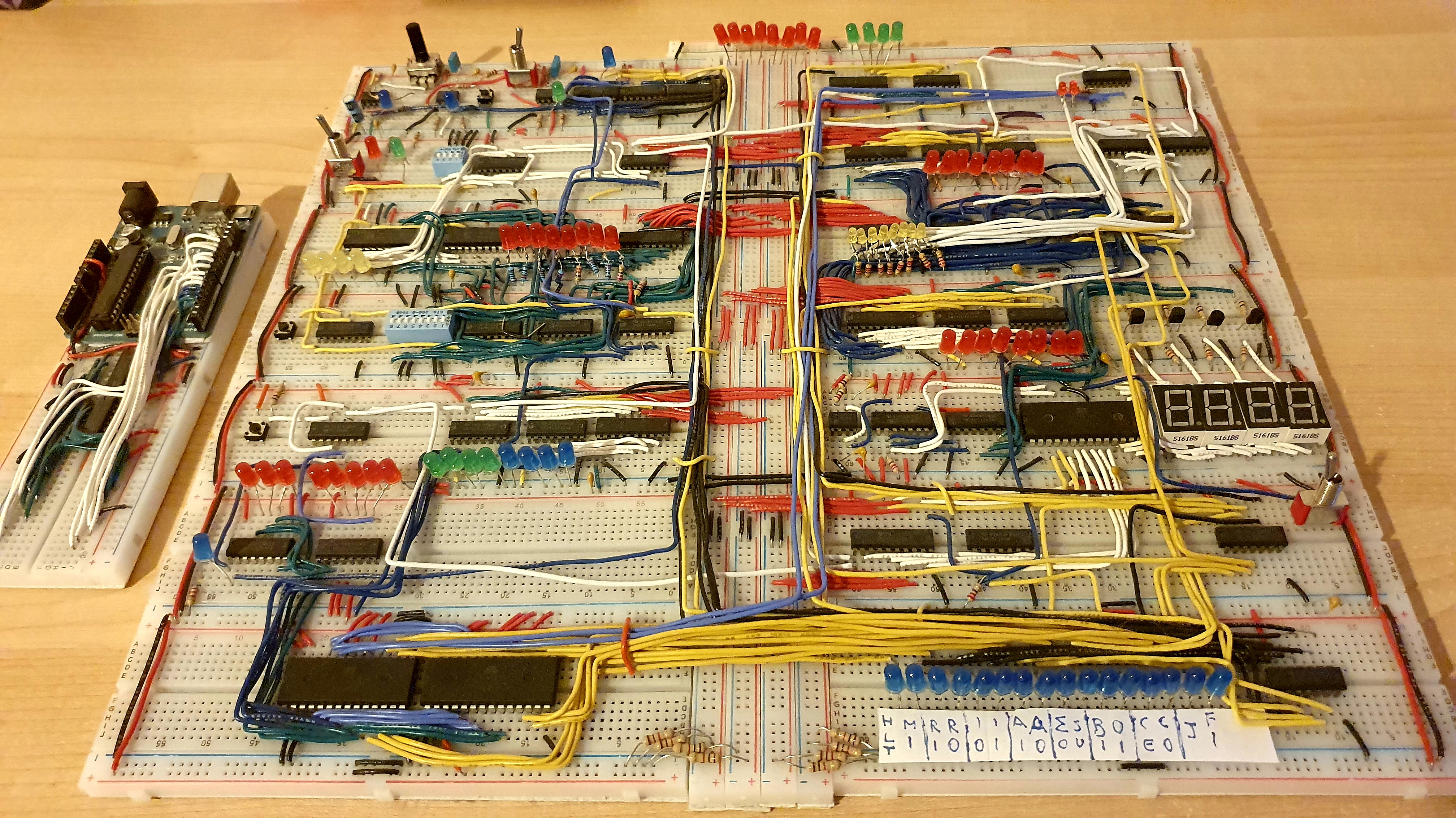
Just a couple of weeks ago I finished my personal 8-bit computer build inspired by ben eater. I learned a lot during the design and troubleshooting process. My build differs only slightly from ben eater’s one. I had to make some minor changes due to different components I used and to fix some problems I was having. In this post I want to list all of the problems I faced with my build. In the meantime here’s the final result:
Doubled Bistable-Clock resistor (2M OHM)
The monostable clock circuit is used to manually trigger a clock-pulse. This is used for example to single-step forward the execution. My problem was that sometimes while pressing the button only once, I was getting two or more clock pulses. After Testing for a while I found out that ben’s de-bouncing circuit only works on the rising edge of the clock. What this means is that if we hold the button pressed for too long keeping the clock high, and then suddently release it, there will be no de-bouncing in place. A simple fix that worked for me was to simply extend the clock high time by increasing the resistance connected to the discharge pin. At the end a 2M Ohm resistor was enough.
Note: This fix is just a workaround. By keeping the button pressed and thus the clock high for long enough, I still sometimes get a double clock pulse when releasing the button.
Buffering edge-detection circuit
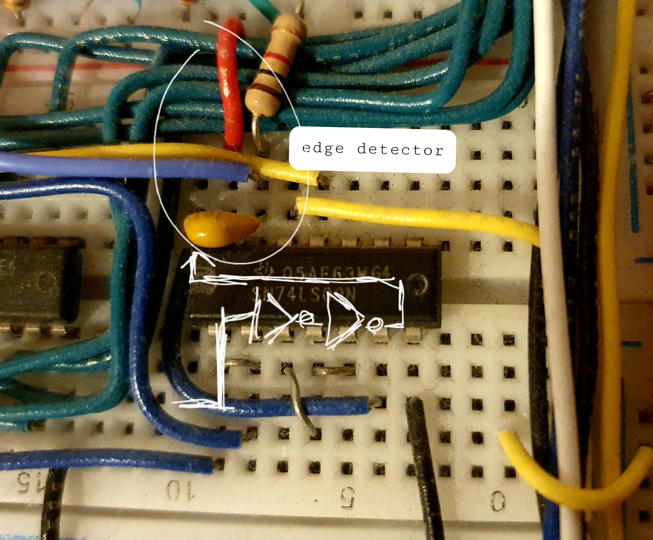
While building the RAM module, I faced a similar issue. The simple edge-detection circuit has a little problem. While it correctly detects a rising edge by charging a capacitor, the same capacitor also needs to discharge and this happens on the falling edge of the clock. Sometimes this causes some fluctuations and double clock pulses. By inverting the original clock pulse two times through a NOT gate, we will isolate the edge detector form the rest of the circuit. There was already a 4-NAND gate circuit nearby wich used only one gate so I ended up using that instead of having to buy another NOT gate.
Common anode 7 segment displays (instead of common cathode)
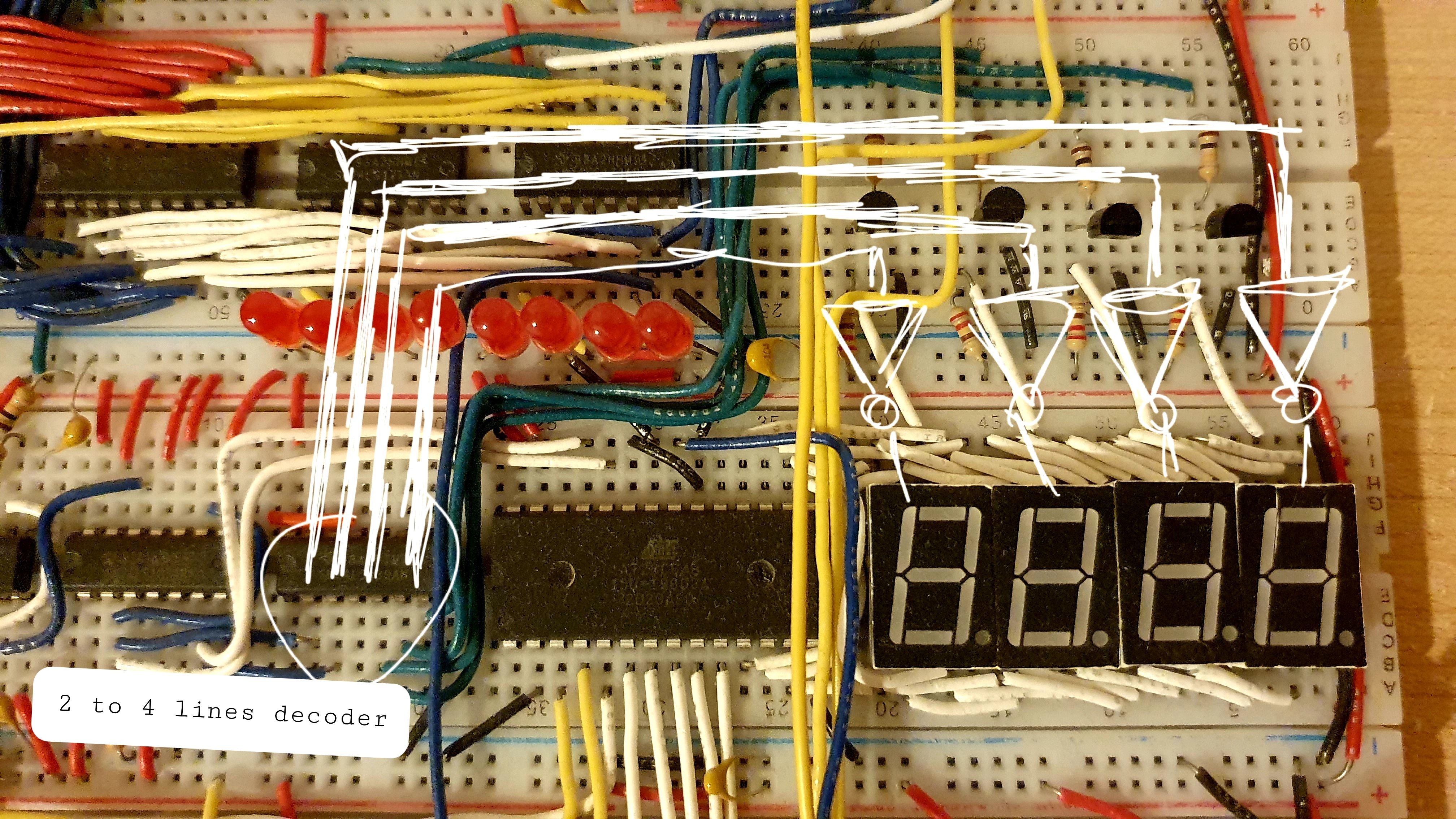
This was my fault. I bought 7 segment displays witch where common anode as opposed to common cathode. Ben’s design multiplexes through the digits by using a 2 to 4 line decoder. Once every four ticks, the Vcc corrisponding to a specific digit is pulled-low and thus turns on. In my case to turn on a digit it’s power source needs to be pulled-up. Simply putting the decoder’s output through some inverters will do the job. Also the eeprom that maps a binary value to the seven segment digits needs to take this into account by inverting the outputs.
HLT Signal Latched on Rising Edge
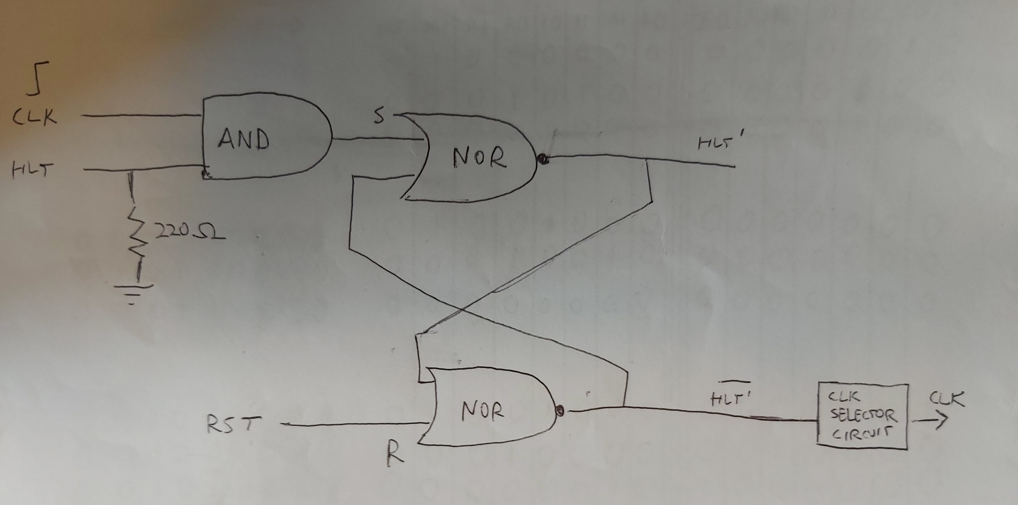
I found that some control signals where very instable. Probably the cause it’s that when the EEPROM changes address to change the set of microinstructions, the outputs are floating for a moment during the switch. Note that I don’t have an oscilloscope and couldn’t verify my assumption. Normally this isnt’ a problem because the contol signals are stable during the falling edge of the clock, when they execute. Howerver some signals like the HLT signal are more sensitive. If this signal gets HIGH at any time the clock is also HIGH, the clock can quickly turn off and on again, causing a double pulse. I tried to design and build a filter circuit for the HLT signal, that latches it only on the rising Edge of the clock and than needs to be manually reset. This however caused the hlt signal to be suddently triggered sometimes at high clock speeds. See next section to know my soultion.
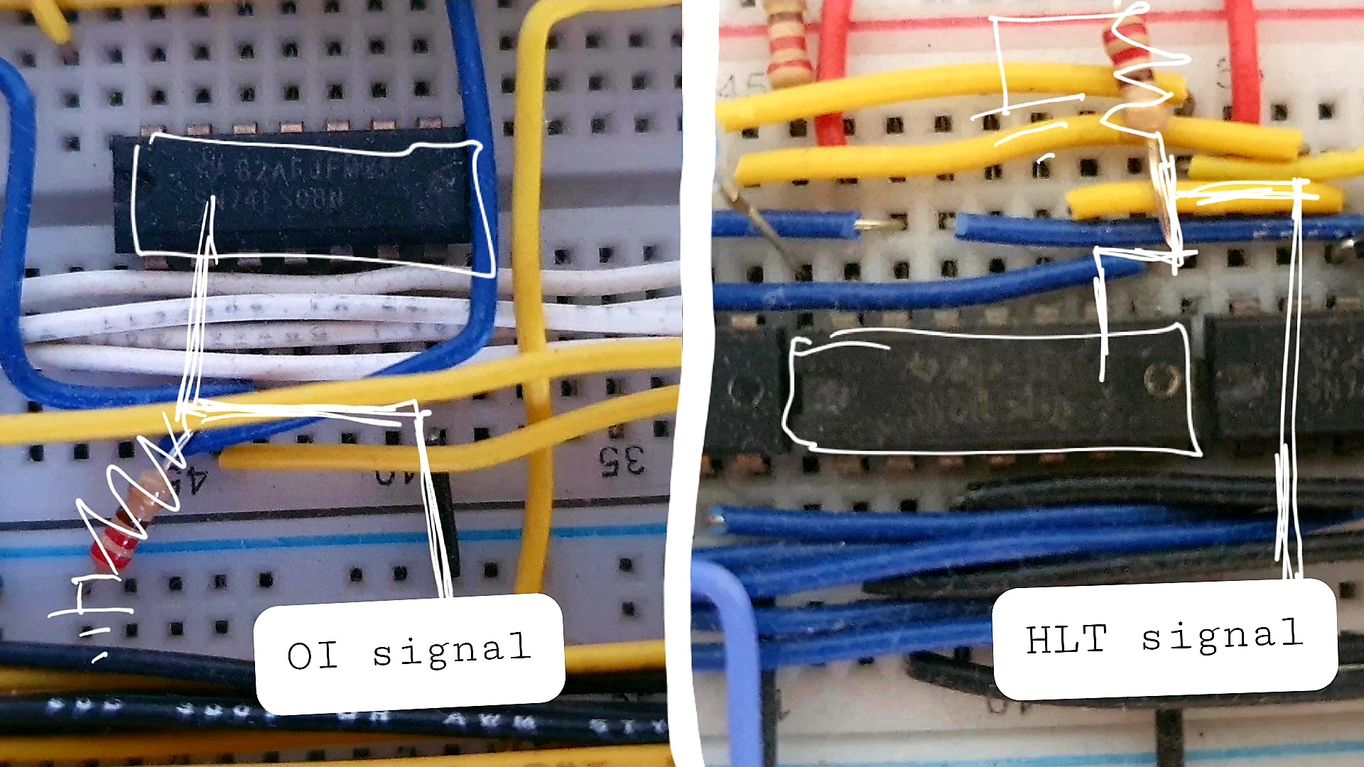
220 Ohm Resistor on Floating Lines (HLT and OI)
Another control line that gave problem when floating was the OI signal. At the end, I solved this and the above problem by simply pulling the control lines output low using 220 Ohm.
Power supply
Make sure to use the right power supply. I initially used an old charger and it was supplying half of the current the circuit needed. This can damage both the circuit and the charger. Switching to the right power supply immediatly solved a lot of my powering issues. Also make sure to double or even triple you power lines to make everything stable enough. I also added 100 nF capacitors between Vcc and Ground on every row. Connecting your led’s through 220 ohm resistors to ground also helps (In ben’s design they are directly connected).
Conclusion
I learned a lot by sticking to this project and suggest anyone interested in computers and electronics to start this or another project too. Also I would like to thank the reddit comunity wich helped me a lot in this journey and don’t forget to check out ben’s youtube channel and website! In this state, the computer need to be manually programmed every time it’s powered on. I’m planning to build an automatic programmer using an arduino to extend the project. Follow me if you like the idea!